Simulation of Electron Beam Physical Vapour Deposition using Direct Simulation Monte Carlo Method
A gas turbine engine is commonly used in aircrafts and for electricity generation. Turbine blades are made from high-strength materials, which can withstand extreme temperature (up to 1500oC) and pressure conditions (up to 40 bars). Thermal barrier coatings (TBCs) are applied to improve thermal performance of blades. Electron Beam Physical Vapour Deposition (EBPVD) is widely used for deposition of TBC due to greater strain tolerance and better thermal shock performance.
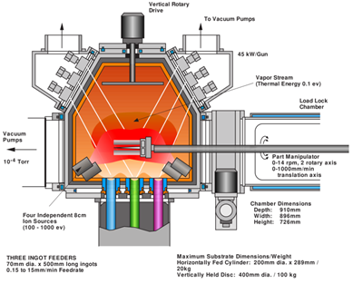
Figure 1: Schematic of EBPVD process; Copyright: Pollution Prevention Infohouse
TBC deposition in EBPVD process involves evacuating the chamber to a base pressure of 0.001 Pa; see Figure 1. The ingots, with diameter ∼5 cm and made up of the coating material, are placed at the bottom of the chamber. The substrate is heated to desired temperature of 1273 K using the electron beam heaters. Oxygen is introduced in the chamber until the chamber pressure reaches 0.13 Pa. Coating material is evaporated from the ingots and deposits on the substrate. The process is repeated until a desired level of coating is achieved.
Under the given operating conditions, the Knudsen number, defined as ratio of mean free path and characteristic length scale, varies from 0.08 at room temperature to 122 at 4570 K (boiling temperature of coating material, i.e. yittria-stabilized zirconia). This indicates that except for the narrow region close to the sublimation zone, the flow inside the vapour plume inside the reactor follows free molecular regime.
Due to high Knudsen number and large temperature gradients, we carry out fluid flow simulations via our in-house direct simulation Monte Carlo (DSMC) code. DSMC is a molecular simulation method which solves Boltzmann’s equation. SankhyaSutra DSMC solver allows for multiple collision models for gas interaction and various boundary conditions (inflow, outflow, pressure and wall). Optimized for parallel execution, the solver can be used for internal and external flows with any geometric shapes and multicomponent gaseous mixtures.
To illustrate the capabilities of SankhyaSutra’s DSMC solver for simulation of EBPVD process, we consider line of sight region around the airfoil; see Figure 2 for schematic. The airfoil of chord length 0.2 mm is maintained at 1273K, while the gas inlet temperature at the bottom is 2500 ℃. The walls of the chamber are considered to be adiabatic. The inlet velocity of the gas is taken as 50 m/s.
Figure 2: Temperature variation
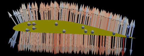
Figure 3: Deposition Height on Airfoil
The gas molecules colliding with the airfoil surface get deposited with certain probability. This creates a relatively low pressure region around the airfoil; hence the gas flow is directed towards the airfoil. As the surface is maintained at 1273K, the temperature gradient is developed close to the airfoil, as depicted in Fig. 2. The deposited material on the surface leads to slight variation in the height of the deposition as shown in Fig. 3. The arrows are pointed normal to the surface and the length and color of the arrows show the deposition height. Both the plots show the microscopic variations in the simulation quantities can be captured well with SankhyaSuytra DSMC solver.